Electrical System Overview
RoboRIO
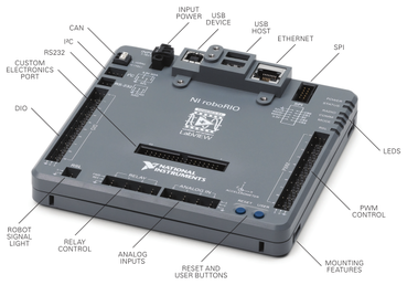
- Xilinx z-7020 CPU with a Dual Core ARM Cortex A-9 processor and FPGA combination
- 256MB DDR3 RAM
- 512MB nonvolatile storage(for programs)
- 2 Host USB ports (For cameras and other external USB hardware)
- 1 10/100BaseT Ethernet connection(for robot communication)
- Up to 8 Analog Inputs(4 on Analog In Header/ 4 on Expansion Port)
- 2 Analog Outputs(on the Expansion Port)
- Up to 16 Digital IO ports(10 on DIO Header/ 6 on Expansion Port)
- 10 Pulse Width Modulation(PWM) Ports(for motor control)
- 4 Relay Ports(for directional motor control)
- Other communication types available including RS232, I2C, SPI, and CAN
Power Distribution Board(PDB)/Power Distribution Panel(PDP)
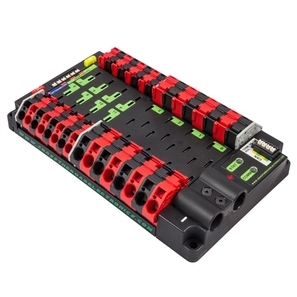
- 12v DC Input designed for FRC-legal batteries
- 8 40 Amp Protected Channels(For high draw situations, like CIMs
- 8 20/30 Amp Protected Channels(For smaller motors, like MiniCIMs and window motors)
- 1 20 Amp Protected Channel(shared between the Pneumatics Control Module(PCM) and the Voltage Regulator Module(VRM)
- 1 10 Amp Protected Channel(for the RoboRIO)
- 1 CAN Bus (For feedback to the RoboRIO)
Voltage Regulator Module(VRM)
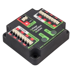
- 1 12v DC Input(From the PDB/PDP dedicated 20 Amp connection)
- 2 5v outputs; 500mA limit
- 2 5V outputs; 2 Amp limit
- 2 12v outputs; 500mA limit
- 2 12v outputs; 2 Amp limit
Pneumatic Control Module(PCM)
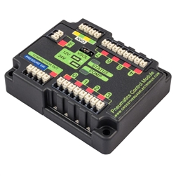
- 1 CAN Bus connection(for RoboRIO control)
- 1 12v Input(From the PDB/PDP dedicated 20 Amp connection)
- 1 Pressure Switch Input
- 8 Solenoid Outputs(12v/24v operation selectable with jumper)
- 1 Compressor DC
Robot Wireless Radio
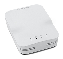
- Max combined speed of 450Mbps(150 + 300)
- 2.4GHz 802.11b/g/n + 5GHz 802.11a/n
- Approximate range indoors : 50-100ft(Through 2-3 walls)
- Approximate range outdoors : 400ft
- 802.3af Compliant for Power over Ethernet at 24v
Motor Controllers
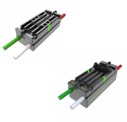
- Minimum/Maximum Input Voltage : 6-16v
- Continuous Current : 60 Amp
- Surge Current : 100 Amp (Max 2 Seconds)
The following specifications apply to the Talon SRX:
- Minimum/Maximum Input Voltage : 6-28v
- Continuous Current : 60 Amp
- Surge Current : 100 Amp (Max 2 Seconds)
- On board sensor inputs and Proportional - Integral - Derivative(PID) control make complex motor control accessible to all teams
- Supports PWM, CAN, SPI, and USART for motor control
Sensors
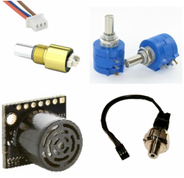
- Switches
- Encoders (Top left image)
- Ultrasonic Sensors
- Photoswitches
- Potentiometers (Top right image)
- Proximity (Lower left image)
- Analog pressure switch (Lower right image)
- Gyroscopes
- Accelerometers (There is a 3 Axis Accelerometer built into the RoboRIO)
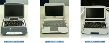
Driver's Station
Bringing It All Together
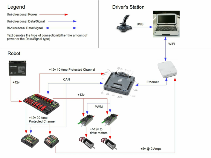
The Driver's Station is connected to the robot by WiFi and then the Open-Mesh Access Point connects directly to the RoboRIO through Ethernet.
The PDB/PDP provides power to each of the devices, directly or indirectly through the VRM. There is a 20 Amp Protected Channel for the PCM and VRM, a 10 Amp Protected Channel for the RoboRIO. The VRM provides power to the robot's Open-Mesh Access Point, and each of the motor controllers have there own 40 Amp connection on the PDB/PDP with an associated Snap Action Breaker.
The PDB/PDP and PCM communicate with the RoboRIO via CAN (Controller Area Network) to provide feedback and control for each of the devices. The motor controllers communicate with the RoboRIO via PWM.
Code To Make The Example Work
import edu.wpi.first.wpilibj.IterativeRobot;
import edu.wpi.first.wpilibj.Joystick;
import edu.wpi.first.wpilibj.Talon;
//The basic implementation of robot control for two motors
public class Robot extends IterativeRobot {
//Create the two motorcontrollers
private Talon t1;
private Talon t2;
//Create the joystick
private Joystick j1;
public void robotInit() {
t1 = new Talon(0);//Create the first motor controller and specify that it's on PWM 0
t2 = new Talon(1);//Create the second motor controller and specify that it's on PWM 1
j1 = new Joystick(0);//Create the joystick and specify that it's connected to USB 0
}
//Unused
public void autonomousPeriodic() {
}
//Called every 20ms to make your robot do things during the teleoperated period
public void teleopPeriodic() {
t1.set(j1.getX());//Make the first motor move based on the Joystick's X axis
t2.set(j1.getY());//Make the second motor move based on the Joystick's Y axis
}
//Unused
public void testPeriodic() {
}